The process of renovating the wayside power rails began this week. The previous way of connected the copper wayside power rails is shown in Figure 1. One of the problems is that the position of the overlapping is not consistent throughout each joint on the half-scale model. Therefore, the collector shoe could glide from a higher rail to a lower rail at one joint, but glide from a lower to higher rail at another joint. The collector shoe is unable to glide from a lower to higher copper rail because the shoe would crash into the joint and prevent it from gliding. In addition, the screw at each joint sticks out just enough to get the shoe caught on the screw even with the modified collector shoes.

Figure 1: Original way of joining together the copper rails. (Drawn by Tan Ho)
The original design of the wayside power rails is retained as much as possible to decrease the amount of time needed to renovate the power rails. The prior design that consisted of overlapping the copper rails at the joints is kept to avoid the need to remove all the copper rails from the PVC pipes. However, the overlapping position is changed according to the direction that the collector shoe will glide. The goal is to get the collector shoe to only glide from a higher copper rail to a lower copper rail at each joint, which is shown in Figure 2. The arrow indicates the direction that the collector shoe glides. A slightly larger drill bit is also used to countersink the existing holes on the copper rails. The result is screws that are flush with the surface of the copper rail.

Figure 1: Direction that the collector shoes glide. (Drawn by Tan Ho)

Figure 1: Original way of joining together the copper rails. (Drawn by Tan Ho)
The original design of the wayside power rails is retained as much as possible to decrease the amount of time needed to renovate the power rails. The prior design that consisted of overlapping the copper rails at the joints is kept to avoid the need to remove all the copper rails from the PVC pipes. However, the overlapping position is changed according to the direction that the collector shoe will glide. The goal is to get the collector shoe to only glide from a higher copper rail to a lower copper rail at each joint, which is shown in Figure 2. The arrow indicates the direction that the collector shoe glides. A slightly larger drill bit is also used to countersink the existing holes on the copper rails. The result is screws that are flush with the surface of the copper rail.
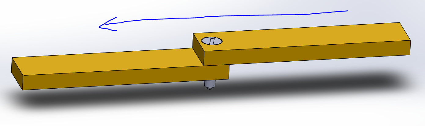
Figure 1: Direction that the collector shoes glide. (Drawn by Tan Ho)
Comments
Post a Comment